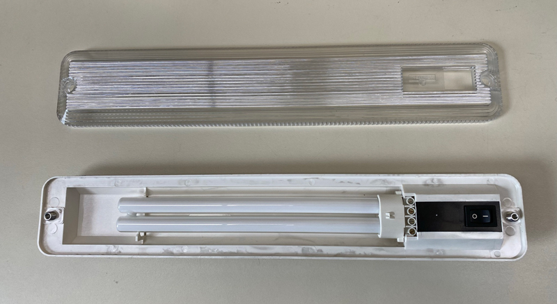
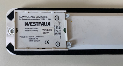
There are two interior cabin lights in our 2003 Weekender. These use fluorescent bulbs and consume about 11 watts of power. That’s a relatively minor drain on our auxiliary battery, but a more important issue is the availability of replacement bulbs for the fixture. These bulbs are 4-pin design that are secured to the fixture with set screws. As far as I know our bulbs are the original, and after doing research I found that replacements are hard to find and are very expensive.
That made me start looking for an alternative to the fluorescent bulbs, and so I started searching online. I found that a lot of RV owners are changing out their fluorescent lighting to LED. I found a really good thread on The Samba.com that described what other owners did, so I decided to give it a try.
Choosing the right LEDs
One of the first things I had to do was get up to speed on LEDs. There are several things to consider:
What color do you want? (warm, natural, daylight). These are expressed in terms of the temperature in degrees Kelvin.
How much light do you need (measured in lumens)
What kind of LED do you need (normal, waterproof, etc.)
The stock fluorescent light in our Weekender uses 11 watts of power. I had to search to find the lumen output, but it appears to be 400 lumens. LED strip lights come in two main densities, measured in LEDs per meter. The standard density is 30/meter with an output of 540 lumens/meter. The high density is twice that.
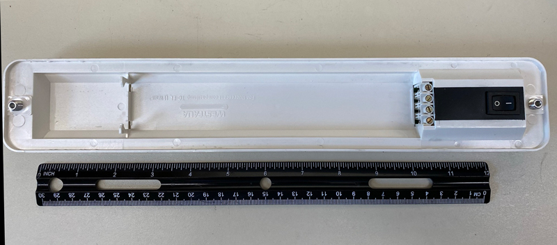
The space available on the fixture measured 10″ x 1-5/8″. The standard density LED strips can be cut every 4″, so we could have 8″ strips in there. Each 8″ strip contains 6 LEDs, and the lumen output of each is 120 lumens, so 3 of these strips would give us 360 lumens, which is close to the 400 lumens in the fluorescent bulb.
I ended up getting a full reel (16.4 feet) of warm white (3000K) LED strips with a density of 30 LEDs per meter. These are called IP20 Flex Strips. I bought these plus the wiring accessories at LEDSupply.com.
Removing the ballast electronics
The fluorescent bulb ballast electronics need to be removed for this conversion. This is done from the back of the fixture. There is a plastic nameplate cover that must be removed first. It snaps out by using a small screwdriver to pry it up over the tabs. Once this is removed the electronic circuit board will be visible.
Back of fixture showing cover over circuit board.
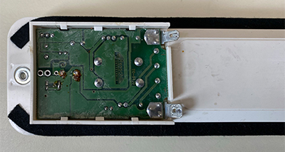
Circuit board exposed after removal of cover.
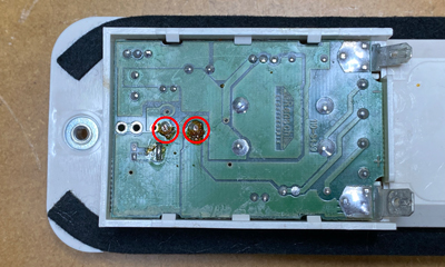
The circuit board is attached to the switch on the front of the fixture by two solder joints. These solder joints mechanically attach the whole board to the cavity. The two solder joints are shown in the photo below. After de-soldering these two joints, the circuit board can be removed by pushing it out starting with the four screw terminals. Then use a screwdriver to push it out the rest of the way.
Close up of circuit board showing the two solder joints for the power switch. Unsolder these joints to remove the circuit board.
After removing the circuit board, the power switch can be removed by popping it out to the front of the fixture. This switch has thin wires to connect it to the circuit board which aren’t very useful for other terminations.
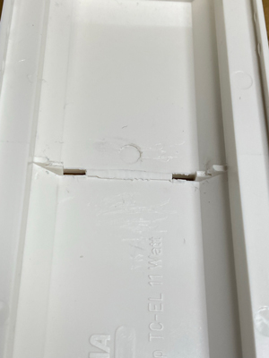
The next step I did was to remove the fluorescent tube clips from the cavity of the fixture. I used a pair of wire cutters to trim the two ears. I also trimmed the ledge portion back so that it would be flush with the back of the cavity so that the LED strips would have a continuous surface to attach to.
Installing the LED Strips
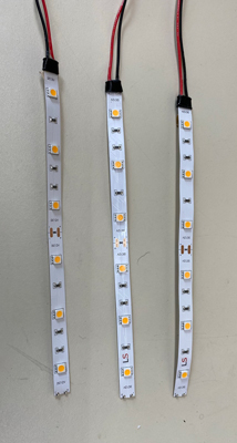
The next step was to cut three LED strips and solder lead wires to the ends. I also installed heat shrink tubing over the solder points to protect the exposed solder pads. I used #20 stranded wire that I had bought with the LEDs. The LED strips were 6 LEDs each.
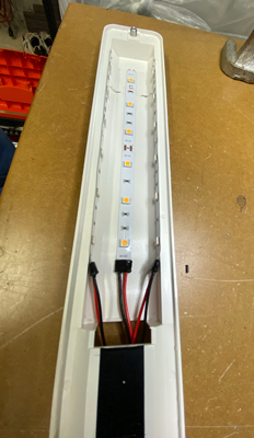
Each strip has a self-adhesive backing, so installing them in the fixture was simple. I chose to put them as shown in the photo: Two on opposing sides (walls) and one on the bottom of the cavity. I tried different configurations using masking tape to hold the strips in place and then powered on the LEDs using a power supply. I found that this configuration produced the best light. The resulting light was more diffuse than putting all the strips on the bottom, and I liked that better.
LED Strips with wire leads soldered on the terminals. Heat shrink tubing installed over solder joints.
LED strips installed in fixture. Two were put on the opposing sides and one on the bottom.
Replacing the Switch
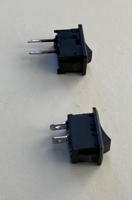
The next step was to put in a new switch. The old switch is a single pole, single throw (SPST) rocker switch. It measured 21 mm x 15 mm and was rated at 6 amps at 125-250 VDC. This switch has spring clips on the sides to hold it in place in the mounting hole.
I did a search on the Internet and found new switches with the design, size and rating as the old one – but with terminal lugs for quick disconnect terminations.
Here is the Amazon listing for these switches. These also have the shoulder spring snaps, and they fitted perfectly into the existing hole.
Old switch (top) has wires that were soldered to the circuit board. New switch (bottom) has lugs for quick connect terminals.
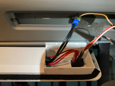
Terminating the LED Lead Wires
The leads from the LED strips were trimmed and stripped, and then these were terminated with quick-disconnect terminals. The positive (red) wires were terminated with a female terminal to fit on the switch lug. The negative (black) leads were terminated with a male terminal. The male terminal had to be narrowed down to fit the existing terminal in the wiring harness.
View of completed fixture connected to the existing wiring.
View of completed fixture connected to the existing wiring.
Testing the completed lights
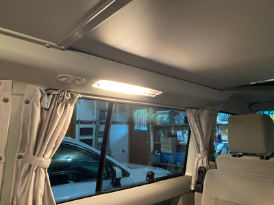
When both fixtures were finished they were reinstalled in the cabin. Then came the final step: testing! The light from the fixture is great. The color is nice and warm and the illumination level is excellent. It seems to be a bit brighter than the old fluorescent bulb, but who knows how old that bulb was!
Here is the finished light with the LEDs turned on.
Energy Savings from the LED Lights
Before I started the project I measured the current draw of the fluorescent fixtures so that I could compare them to the converted LED version.
The old fixture drew 0.9 amps at 12 volts, or 11 watts. The new LED fixture draws 0.38 amps at 12 volts, or 4.6 watts. That’s about 60% less power and means you can run both lights for less power than one of the old fixtures.